Da Merlin un progettino con Arduino per Analizzatore
- Kagliostro
- Amministratore
- Messaggi: 9633
- Iscritto il: 03/12/2007, 0:16
- Località: Prov. di Treviso
Da Merlin un progettino con Arduino per Analizzatore
Ho appena visto sul sito di Merlin che, sulla scia dell'U-Tracer, ha realizzato un analizzatore per valvole a basso costo basato su Arduino
Per coloro che ne capiscono della materia o fossero anche solo interessati a dare un'occhiata
ecco il link
http://www.valvewizard.co.uk/analyser.html
Magari i più smaliziati potrebbero riconoscere delle parti che si adatterebbero al vecchio e mai portato a termine
provavalvole elettronico di cui abbiamo discusso qui sul forum
Non sapete quanto mi dispiaccia non capirci nulla
K
Re: Da Merlin un progettino con Arduino per Analizzatore
Grazie Franco!
Cerco anche di capire perchè abbia usato due Arduino Nano invece di un Arduino più performante come ingressi/uscite/calcolo/porte di comunicazione. Costi e reperibilità?
Stasera se riesco ti posto una breve spiegazione di cosa fa questo sistema. Ho visto alcune cose interessanti.
Cerco anche di capire perchè abbia usato due Arduino Nano invece di un Arduino più performante come ingressi/uscite/calcolo/porte di comunicazione. Costi e reperibilità?
Stasera se riesco ti posto una breve spiegazione di cosa fa questo sistema. Ho visto alcune cose interessanti.
Re: Da Merlin un progettino con Arduino per Analizzatore
Ciao Franco, dividerò il codice a "blocchi" così che sia di semplice comprensione.
Il blocco qui sotto avvisa (#define) il microprocessore che utilizzerà le seguenti variabili (in maiuscolo).
Dopo il simbolo "//" c'è la spiegazione a chi legge il software di che cosa sia quella variabile.
Il blocco qui sotto avvisa (#define) il microprocessore che utilizzerà le seguenti variabili (in maiuscolo).
Dopo il simbolo "//" c'è la spiegazione a chi legge il software di che cosa sia quella variabile.
Codice: Seleziona tutto
#define DIODE_MODE 1
#define TRIODE_MODE 2
#define PENTODE_MODE 3
#define MIN_HV_INCREMENT 5 //Minimum increment between each high-voltage datapoint in a sweep, in volts
#define MASTER 1 //For when hardware ID pin is high
#define SLAVE 0 //For when hardware ID pin is low
#define MASTER_ADDR 0x0A //I2C Address of the MASTER Arduino
#define SLAVE_ADDR 0x0B //I2C Address of the SLAVE Arduino
#define DAC1_ADDR 0x60 //I2C Address of one MCP4725, by default pin A0 is pulled to GND.
#define DAC2_ADDR 0x61 //I2C Address of other MCP4725; its pin A0 must be pulled HIGH to make address 0x61 (also remove pull-up resistors). Note that the breakout board uses the MCP4725A0.
//NB: I2C can send 32 ints per transmission.
#define HARDWARE_ID_PIN 12 //High for master, low for slave
#define VH_PIN A2 //Heater-voltage sense from buck regulator
#define IH_PIN A3 //Heater-current sense from buck regulator
#define PWM_PIN 6 //PWM drive signal to buck regulator MOSFET
#define CHARGE1_PIN 8 //Drive to high-voltage charge MOSFET
#define DISCHARGE1_PIN 11 //Drive to high-voltage discharge MOSFET
#define FIRE1_PIN 7 //Drive to 'apply high voltage' MOSFET
#define VA1_PIN A6 //High voltage sense 1
#define VA2_PIN A7 //High voltage sense 2
#define IA1_HI_PIN A1 //Small anode-current sense (large sense resistance)
#define IA1_LO_PIN A0 //Large anode-current sense (small sense resistance)
#define IA2_HI_PIN A3 //Small anode-current sense (large sense resistance)
#define IA2_LO_PIN A2 //Large anode-current sense (small sense resistance)
#define DISCHARGE2_PIN 4
#define FIRE2_PIN 2
#define CHARGE2_PIN 3
#define LV_DETECT_PIN 11 //Pin to detect if heater power supply is present
Re: Da Merlin un progettino con Arduino per Analizzatore
Qui si dice che bisogna caricare sull'Arduino le seguenti librerie, che non sono altro che sottoprogrammi che fanno determinate funzioni.
Per esempio, la libreria "math" è un po' come far laureare Arduino in matematica, e quindi chiedergli di eseguire determinati calcoli che altrimenti richiederebbero di "spiegargli" come fare, procedura lunga e non alla portata di tutti.
Codice: Seleziona tutto
#include <math.h>
#include <avr/pgmspace.h>
#include <Wire.h> //Include the Wire library to talk I2C
Re: Da Merlin un progettino con Arduino per Analizzatore
Qui definisce le variabili che utilizzerà nel programma per svolgere le sue funzioni, e ti dice il tipo di variabile:
Below is a list of the data types commonly seen in Arduino, with the memory size of each in parentheses after the type name. Note: signed variables allow both positive and negative numbers, while unsigned variables allow only positive values.
boolean (8 bit) - simple logical true/false
byte (8 bit) - unsigned number from 0-255
char (8 bit) - signed number from -128 to 127. The compiler will attempt to interpret this data type as a character in some circumstances, which may yield unexpected results
unsigned char (8 bit) - same as 'byte'; if this is what you're after, you should use 'byte' instead, for reasons of clarity
word (16 bit) - unsigned number from 0-65535
unsigned int (16 bit)- the same as 'word'. Use 'word' instead for clarity and brevity
int (16 bit) - signed number from -32768 to 32767. This is most commonly what you see used for general purpose variables in Arduino example code provided with the IDE
unsigned long (32 bit) - unsigned number from 0-4,294,967,295. The most common usage of this is to store the result of the millis() function, which returns the number of milliseconds the current code has been running
long (32 bit) - signed number from -2,147,483,648 to 2,147,483,647
float (32 bit) - signed number from -3.4028235E38 to 3.4028235E38. Floating point on the Arduino is not native; the compiler has to jump through hoops to make it work. If you can avoid it, you should. We'll touch on this later.
Codice: Seleziona tutto
/************************************************************
* GLOBAL VARIABLES
************************************************************/
#define ARRAY_LENGTH 10
int targetValues[ARRAY_LENGTH]; //Array to hold target values (array lenth must be less than 32 ints or 16 unsigned ints owing to I2C limit)
int measuredValues[ARRAY_LENGTH]; //Array to hold measured values (array lenth must be less than 32 ints or 16 unsigned ints owing to I2C limit)
int testMode = 0;
float heaterVolts = 0;
int dataPoints = 2;
int maxAnodeVolts = dataPoints * MIN_HV_INCREMENT;
float maxGridVolts1 = 0;
float voltsPerStep = 0;
int screenVolts = 0;
int ulPercent = 0;
float maxGridVolts2 = 0;
int duty_cycle = 0; //Duty cycle of buck converter
boolean hardware; //Will be set to 1 if hardware ID pin is high (MASTER), else 0 (SLAVE).
const char selectTestMessage[] PROGMEM = {"Select test mode:"};
const char diodeMessage[] PROGMEM = {"[Diode / double diode = 1;"};
const char triodeMessage[] PROGMEM = {"Triode / double triode = 2;"};
const char pentodeMessage[] PROGMEM = {"Tetrode / pentode = 3]"};
const char heaterVoltsMessage[] PROGMEM = {"Set heater to: [up to 24V]"};
const char voltsSymbol[] PROGMEM = {" V"};
const char sweepHV1Message[] PROGMEM = {"Sweep anode(s) from 0V up to: [up to 500V]"};
const char dataPointsMessage[] PROGMEM = {"Number of datapoints per sweep: [not less than 2]"};
const char gridBias1Message[] PROGMEM = {"Step primary grid(s) bias supply from 0V down to: [up to -60V]"};
const char stepSizeMessage[] PROGMEM = {"Step size:"};
const char HV2Message[] PROGMEM = {"Set secondary high voltage supply to: [up to 500V]"};
const char ulMessage[] PROGMEM = {"UL percent: [0% = full pentode; 100% = full triode] "};
const char percentSymbol[] PROGMEM = {" %"};
const char gridBias2Message[] PROGMEM = {"Set secondary grid bias supply to: [up to -60V]"};
const char runMessage[] PROGMEM = {"Run test? [y/n]"};
const char errorMessage[] PROGMEM = {"Error: Parameter out of range?"};
const char columnLabels[] PROGMEM = {"Vb1(V), HV1(V), Ia1(mA), Vb2(V), HV2(V), Ia2(mA),"};
//INDICES FOR BOTH ARRAYS
#define VH 0 //Heater voltage [example: 12.6V = adc391 6.3V = adc195]
#define IH 1 //Heater current
#define VG1 2 //Grid voltage 1 [example: 1V = dac60, 10V=dac605, 20V=dac1210, 30V=dac1815, 40V=dac2420, 50V=dac3020]
#define HV1 3 //Anode voltage 1 [example: 600V=3.97V=adc992 300V=1.98V=adc496 200V=0.76V=330 100V=0.381V=V=adc165]
#define IA_HI_1 4 //Anode current hi 1
#define IA_LO_1 5 //Anode current lo 1
#define VG2 6 //Grid voltage 2
#define HV2 7 //Anode voltage 2
#define IA_HI_2 8 //Anode current hi 2
#define IA_LO_2 9 //Anode current lo 2
/************************************************************
*FUNCTION PROTOTYPES
************************************************************/
void setHeaterVolts();
void setGridVolts();
void chargeHighVoltages();
void print_arrays();
void send_to_slave();
void masterReceiveData(int howMany);
void request_from_slave();
void slaveReceiveData(int howMany);
void slaveAnswerRequest();
void printMeasuredValues(void);
void setTargetValue(int index, float volts);
void calculateSweepValues(int sweepArray1[], int sweepArray2[]);
int checkForUserErrors(void); //returns 1 if the user has entered valid test parameters, else 0
void doMeasurement(void);
void dischargeHighVoltages(void);
void getUserParameters(void);
void printMessage(const char *messageptr);
int getUserInstruction(void);//returns 1 if user request to run test, else 0
Re: Da Merlin un progettino con Arduino per Analizzatore
Questa parte avvia la comunicazione seriale sull'Arduino (quella che manda informazioni tramite USB al PC):
Imposta il pin HARDWARE_ID_PIN come ingresso senza pull-up:
Dice ad Arduino di controllare il riferimento in tensione esterno per la conversione da analogico a digitale:
Interessante escamotage per accelerare il funzionamento dell'Arduino, sebbene alteri i tempi interni (da considerare se programmo dei ritardi)
Codice: Seleziona tutto
/************************************************************
* SETUP
************************************************************/
void setup() {
Serial.begin(9600); //Setup serial interface
Codice: Seleziona tutto
pinMode(HARDWARE_ID_PIN, INPUT);
//I2C SDA is on Arduino Nano pin A4 as standard
//I2C SCL is on Arduino Nano pin A5 as standard. These pins need no further setup.
//By default, analog input pins also need no setup
Codice: Seleziona tutto
analogReference(EXTERNAL); //Use external voltage reference for ADC
Codice: Seleziona tutto
TCCR0B = (TCCR0B & 0b11111000) | 0x01; //Configure Timer0 for internal clock, no prescaling (bottom 3 bits of TCCR0B)
//Makes Arduino run 6.3 times faster than normal. NB: This affects Arduino delay() function!
Re: Da Merlin un progettino con Arduino per Analizzatore
Qui impostiamo un PWM come comando esterno e ripetiamo il segnale sul led dell'arduino per vedere che il risultato sia corretto (col PWM di valore alto il led si illumina maggiormente che non col PWM basso).
Il codice è uguale su entrambi gli Arduino utilizzati, e tramite una configurazione esterna si dice al processore se è colui che comanda e "parla col pc", cioè il Master, oppure lo Slave.
Codice: Seleziona tutto
analogWrite(PWM_PIN, 0); //Make sure PWM output is zero on startup
pinMode(LED_BUILTIN, OUTPUT); //Arduino built-in LED for debugging
Codice: Seleziona tutto
hardware = digitalRead(HARDWARE_ID_PIN); //Identify if this is MASTER (1) or SLAVE (0) Arduino
hardware = 1;
if(hardware == MASTER){
pinMode(CHARGE1_PIN, OUTPUT);
pinMode(DISCHARGE1_PIN, OUTPUT);
pinMode(FIRE1_PIN, OUTPUT);
pinMode(CHARGE2_PIN, OUTPUT);
pinMode(DISCHARGE2_PIN, OUTPUT);
pinMode(FIRE2_PIN, OUTPUT);
digitalWrite(FIRE1_PIN, LOW);
digitalWrite(FIRE2_PIN, LOW);
digitalWrite(CHARGE1_PIN, LOW);
digitalWrite(CHARGE2_PIN, LOW);
digitalWrite(DISCHARGE1_PIN, HIGH); //make sure capacitor banks are discharged ready for first sweep
digitalWrite(DISCHARGE2_PIN, HIGH);
Wire.begin(MASTER_ADDR); //Register I2C address
Wire.onReceive(masterReceiveData); //Interrupt when I2C data is being received
}
else{ //else this is SLAVE hardware
pinMode(LV_DETECT_PIN, INPUT);
analogWrite(PWM_PIN, 0); //Set heater to 0V at start-up
Wire.begin(SLAVE_ADDR); //Register I2C address
Wire.onReceive(slaveReceiveData); //Interrupt when I2C data is being received
Wire.onRequest(slaveAnswerRequest); //Interrupt when master demands a response
}
}
Re: Da Merlin un progettino con Arduino per Analizzatore
Suggerisco poi di saltare per ora questa parte qui sotto, che è il programma principale, e leggersi tutte le parti successive che sono molto ben commentate:
Codice: Seleziona tutto
/************************************************************
* MAIN LOOP
************************************************************/
void loop() {
if(hardware == MASTER){
static int runTest = 0;
while(!runTest){
getUserParameters(); //Ask for user input, returns 1 when ready
runTest = checkForUserErrors(); //Returns 1 if no errors found
}
float sweepTable1[dataPoints];//Stores HV1 voltages to be used during a sweep
float sweepTable2[dataPoints];//Stores HV2 voltages to be used during a sweep
calculateSweepValues(sweepTable1, sweepTable2); //Populate the sweep values
runTest = getUserInstruction(); //user must press 'y' to run test
if(runTest){ //commence test
setTargetValue(VH, heaterVolts); //send again in case anything has changed
send_to_slave();
printMessage(columnLabels);
for(float j = 0; j <= maxGridVolts1; j += voltsPerStep){
setTargetValue(VG1, j);
if(testMode == TRIODE_MODE){//if testing a triode
targetValues[VG2] = targetValues[VG1];//make VG2 supply the same as VG1 supply
}
else{ //else make it constant
setTargetValue(VG2, maxGridVolts2);
}
if(maxGridVolts1 == 0){//if user requested only 0V curve
j++;//stop the test from repeating
}
if(testMode == DIODE_MODE){//if testing a diode
j = maxGridVolts1 + 1;//stop the test from repeating
}
setGridVolts();
for(int i = 0; i < dataPoints; i++){
float nextHV1 = sweepTable1[i];//get next datapoint for HV1 sweep
float nextHV2 = sweepTable2[i];//get next datapoint for HV2 sweep
setTargetValue(HV1, nextHV1);
setTargetValue(HV2, nextHV2);
chargeHighVoltages();
doMeasurement();
request_from_slave();
printMeasuredValues();
}
dischargeHighVoltages(); //sweep is complete
}
}
digitalWrite(LED_BUILTIN, LOW); //for debugging
}
else{ //Else this is SLAVE hardware
setHeaterVolts();
}
} //End of main program loop
Re: Da Merlin un progettino con Arduino per Analizzatore
Prendo questa parte di programma per spiegare come si traduce un programma in Italiano, guardate questa immagine:
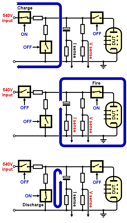
Qui fornisce il titolo a cosa farà la parte successiva del programma, che si chiama chargeHighVoltages
Dichiara (void) la funzione chargeHighVoltages
Spegne tutti i mosfet (buona pratica quando non si sa da quale funzione precedente si arriva
Vedere il partitore di tensione che ha per uscita VA1, per esser sicuro di non eccedere mai i 5V sull'ingresso dell'Arduino:
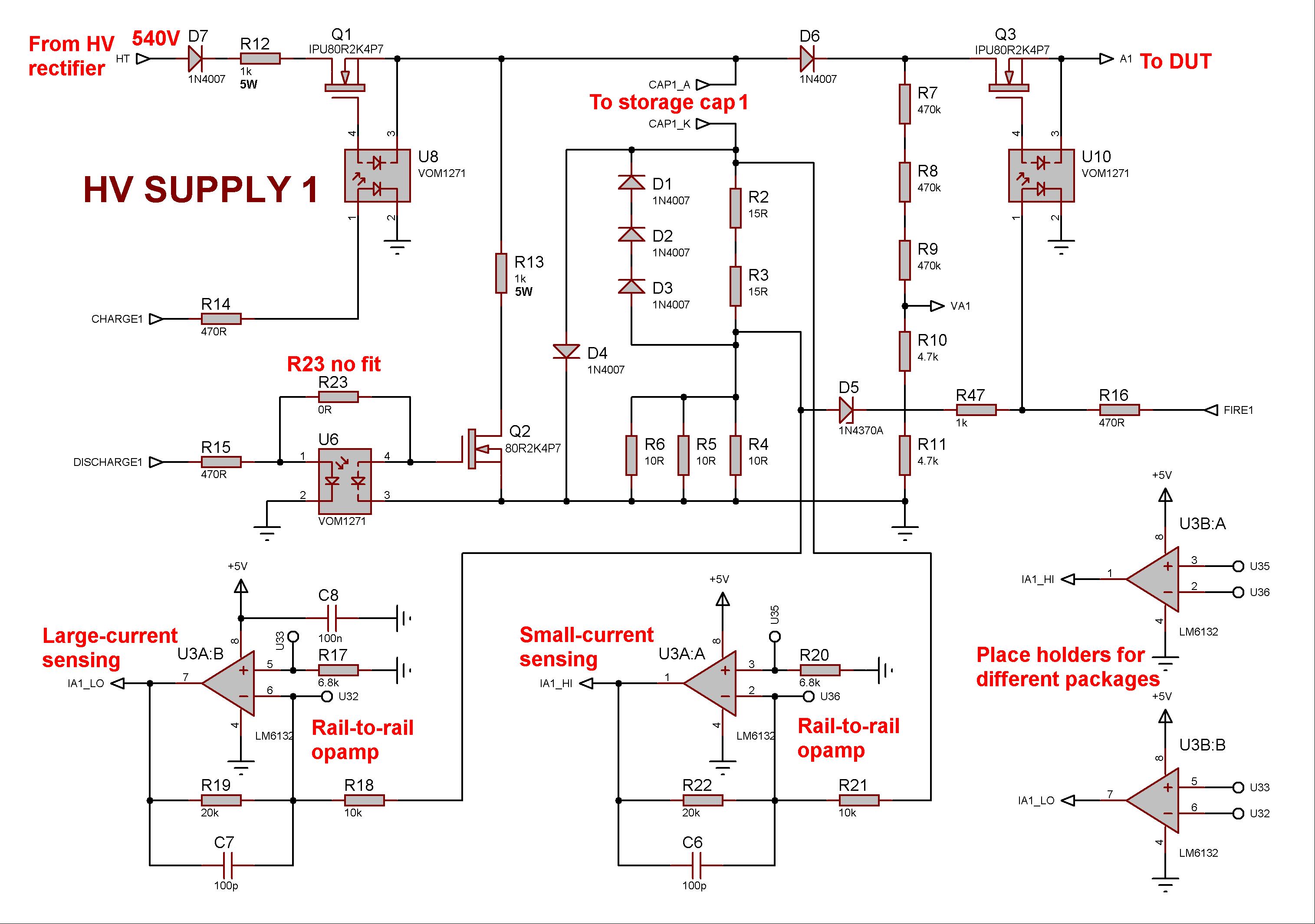
E vedere qui l'ingresso VA1 sull'Arduino Master:
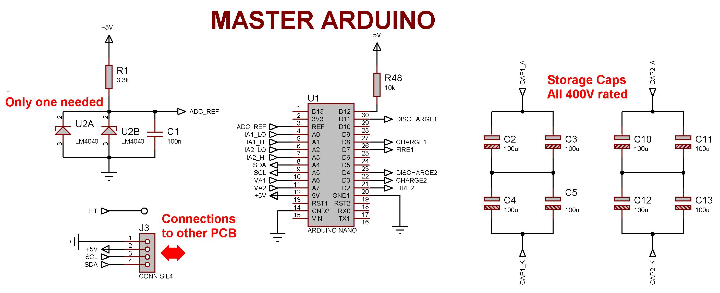
Legge le tensioni ricavate dallo schema precedente (VA1_PIN è appuntol'ingresso di VA1, stessa cosa fa per VA2):
Non carica entrambi i gruppi di condensatori insieme, ma prima carica quelli relativi a HV1 controllando la tensione:
E quando è corretta isola i condensatori dal resto del circuito (vedere sempre prima immagine animata):
Ripete la stessa procedura per il secondo gruppo di condensatori di HV2:
Controlla di nuovo per sicurezza i condensatori del primo banco HV1, che non si siano scaricati nel frattempo.
Qui fornisce il titolo a cosa farà la parte successiva del programma, che si chiama chargeHighVoltages
Codice: Seleziona tutto
/****************************************************************************
* Charges up the high-voltage capacitor banks to the target values
****************************************************************************/
Codice: Seleziona tutto
void chargeHighVoltages(){ //Manages the HV supply
Codice: Seleziona tutto
digitalWrite(FIRE1_PIN, LOW); //Turn off MOSFETs (fail-safe measure)
digitalWrite(FIRE2_PIN, LOW);
digitalWrite(CHARGE1_PIN, LOW);
digitalWrite(CHARGE2_PIN, LOW);
digitalWrite(DISCHARGE1_PIN, LOW);
digitalWrite(DISCHARGE2_PIN, LOW);
E vedere qui l'ingresso VA1 sull'Arduino Master:
Legge le tensioni ricavate dallo schema precedente (VA1_PIN è appuntol'ingresso di VA1, stessa cosa fa per VA2):
Codice: Seleziona tutto
measuredValues[HV1] = analogRead(VA1_PIN); //Measure the high voltage and store the value
measuredValues[HV2] = analogRead(VA2_PIN); //Measure the high voltage and store the value
Codice: Seleziona tutto
//While either storage cap is not charged to the correct voltage, alternately charge each cap
//NB: Both cannot be charged simultaneously or one may hold down the supply to the other.
while((measuredValues[HV1] != targetValues[HV1]) || (measuredValues[HV2] != targetValues[HV2])){
while(measuredValues[HV1] < (targetValues[HV1]-0)) {//If voltage is too low, charge capacitor
digitalWrite(CHARGE1_PIN, HIGH);
measuredValues[HV1] = analogRead(VA1_PIN); //Keep checking the voltage
}
Codice: Seleziona tutto
digitalWrite(CHARGE1_PIN, LOW); //Done, isolate this storage capacitance. It will begin to discharge slowly.
Codice: Seleziona tutto
measuredValues[HV2] = analogRead(VA2_PIN); //Measure the high voltage and store the value
while(measuredValues[HV2] < (targetValues[HV2]-0)) {//If voltage is too low, charge capacitor
digitalWrite(CHARGE2_PIN, HIGH);
measuredValues[HV2] = analogRead(VA2_PIN); //Keep checking the voltage
}
digitalWrite(CHARGE2_PIN, LOW); //Done, isolate this storage capacitance. It will begin to discharge slowly.
Codice: Seleziona tutto
measuredValues[HV1] = analogRead(VA1_PIN);//Check first capacitor bank again
}
Re: Da Merlin un progettino con Arduino per Analizzatore
Piccola nota:
da questo progetto si può sviluppare un sistema che faccia il bias in automatico alle valvole finali ad ogni startup dell'amplificatore.
- Kagliostro
- Amministratore
- Messaggi: 9633
- Iscritto il: 03/12/2007, 0:16
- Località: Prov. di Treviso
Re: Da Merlin un progettino con Arduino per Analizzatore
Ma tu pensa
Grazie per la divulgazione Robi
Franco
Grazie per la divulgazione Robi
Franco
- Kagliostro
- Amministratore
- Messaggi: 9633
- Iscritto il: 03/12/2007, 0:16
- Località: Prov. di Treviso
Re: Da Merlin un progettino con Arduino per Analizzatore
Chi ne capisce potrebbe postare un BOM dei materiali necessari per comporre l'analizzatore
corredato da una piccola descrizione su come vanno assemblati tra di loro per realizzare l'analizzatore
Grazie
K
corredato da una piccola descrizione su come vanno assemblati tra di loro per realizzare l'analizzatore
Grazie
K
Re: Da Merlin un progettino con Arduino per Analizzatore
Prego Franco,
spero aiuti altre persone ad interessarsi all'argomento e postare altri progetti sul forum!
Re: Da Merlin un progettino con Arduino per Analizzatore
Sì, sarebbe una bella idea per chi ne avesse voglia!Kagliostro ha scritto: ↑17/03/2020, 13:05Chi ne capisce potrebbe postare un BOM dei materiali necessari per comporre l'analizzatore